Technical Specification for Automated Flagger System AF-100
Revision 130930
Manufactured by Synergy Technology, LLC - Albemarle, NC USA
September 30, 2013
Subject to Change without notice
Automated Flagger System AF-100 includes:
Quantity Description
1 Main Signal Trailer
1 Remote Signal Trailer
2 Wireless Radio Pendant
1 User Manual
Limited Warranty
Automated Flagger System AF-100 includes:
Quantity Description
1 Main Signal Trailer
1 Remote Signal Trailer
2 Wireless Radio Pendant
1 User Manual
Limited Warranty
Specifications
The Automated Flagger, System AF-100 is self contained and includes two Signal Trailers, each
with Red/Yellow Lens Signal Light and Gate Arm, and two Wireless Remote Pendants.
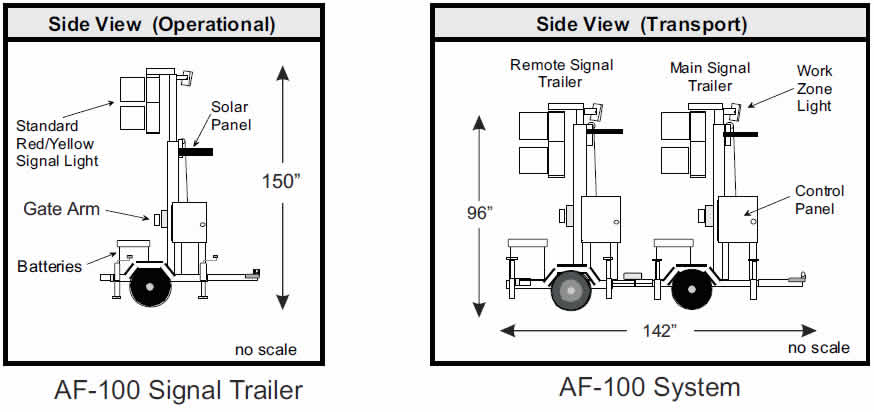
Specification for Red/Yellow Lens Automated Flagger Assistance Device Model: AF-100 Signal Trailer
AF-100 Signal Trailer: (Each system includes a Main Signal Trailer and a Remote Signal Trailer)
Controller:
*Each Signal Trailer includes a Controller featuring three microcontrollers. The main CPU controls the signal lights
and general operating functions. An Conflict Monitor microcontrollers monitors the system for power
issues, Signal Lamp failures, Conflicting Signals and power issues. An independent microcontrollers controls the Gate
Arm function.
- Each Controller features a 4 line LCD which displays:
Signal Trailer Voltage
Instructions for changing Programs
Program in use
Signal Light Status for each trailer
Lamp failure
Signal Conflict
Radio Signal Channel - The Controller features 3 program modes:
Single Operator for two Signal Trailers
Single Operator for one Signal Trailers
Flash Yellow program for Haul Roads and Pedestrian Crossings (All programs are set via a single button (with 5 second safety delay). All program changes must be made when the unit or units are in Red Signal/ Gate Arm down status)
On start up the controller will search for radio signals from other systems that may be in Radio Range.
- The Controller features metal “Vandal Proof Switches” for all control functions.
- The Controller is housed in a lock-able all metal sealed NEMA rated cabinet.
- The Controller wiring meets applicable SAE, UL and ITE standards.
- The Controller contains no screw type terminal connections or other open connections with are subject to
failure in harsh environments conditions and/or vibration. - The Controller features a single Amphonel multipin connector for all electronic connection to the Controller.
This feature simplifies replacement of Controller in the field without special tools or training. - The Controller features a “Sequence” switch that can control the operation from the panel, in the event that a Wireless Radio Pendant is unavailable.
Power Supply:
- Each Signal Trailer feature 3 - 12 volt Deep Cycle 140 amp hour Batteries.
- Each Signal Trailer features an SP-80 solar Panel and Charge Controller
- Each Signal Trailer features a 110 VAC - 10 amp battery charger with 110 VAC connector accessible from the outside of the Battery Cabinet.
- Each Signal Trailer features a lockable, plastic composite Battery Cabinet.
LED Signal Lights:
- The Signal Housing of the Signal Trailer includes a 12” Red and a 12” Yellow (Amber) Signal Light
- Signal Lights are 12 Volt, ITE standard compliant, Light Emitting Diodes (LED)
- The Signal Housing are MUTCD compliant with aluminum construction.
- The Signal Housing includes a compliant backplate.
- A 5 inch amber LED is mounted on the back side of the Signal Housing and indicates the status of the Amber Signal Light to an operator within the work zone.
Gate Arm
- The Gate Arm measures 8 ft in length (plus a 2 ft flag extension), and 5 ½” in height.
- The Gate Arm is counter balanced to reduce power needed to raise and lower.
- The Gate Arm is covered with MUTCD specified 4” x 16” alternating red and silver retro reflective sheeting.
- The Gate Arm folds in half to store in place.
Radio System:
- All radio are high performance, frequency hopping spread spectrum transceivers operating under FCC part 15.247 regulations for the 900 MHZ band.
- Qualified for operation in a temperature range of -40C to +80C.
- Features FHSS technology with Data-Encryption Standards and proprietary software synchronization.
Trailer Frame:
- The Signal Trailer frame features a 2”’ X 4” welded tubing frame with dimension of 48” long and 52” wide.
- The Main Signal Trailer features a 2” X 4” X 42” (length) steel tubing tongue with 2” X 2” steel tubing braces and 4” riser for 2” Ball Hitch Coupler.
- The Remote Signal Trailer features a 2” X 4” X 6”(length) steel tubing tongue.
- Each trailer features a telescoping Signal Light Mast constructed of 2” X 1 ½” square steel tubing with braking winch.
- Each Signal Trailer features a 12 volt trailer lighting system complying with Federal Motor Carrier Safety Regulations 393.
- Each Signal Trailer will be primed with Epoxy Primer and painted with Marine Grade Federal Standard 595a
“Highway Orange” polyurethane paint. - Each Signal Trailer features a 2500 lbs rated axle and 13” tires.
- Each Signal Trailer features (4) swivel screw style jacks to level the trailer.
Wireless
- The Wireless Radio Pendent is housed is an all aluminum sealed housing
- The Wireless Radio Pendent features stainless steel “Vandal Proof Switches”
- The Wireless Radio Pendent features switches for Signal Sequence and Emergency Horn.
- External Antenna for extended operational distance.
- The Wireless Radio Pendent features a 18,400 mAh, Ni-MH battery pack for 2-4 year operation
- A battery pack charger with 110VAC and 12 VDC connections is provided.
(*In addition each controller features a manual backup switch to operate the Signal Trailer and/or System in the event
of a Wireless Radio Pendent Failure.
Operation Manual:
Each Signal Trailer and/or System will come with a complete operation manual.
Warranty:
Each Signal Trailer and/or System come with a one year limited manufacturer warranty.
AF-100 Optional Equipment:
Part Number Description
EJ - Extended heavy duty jack with drop down extension for faster set up and extended length, (for applications with severe shoulder drop offs)
EH - 120 dB Emergency Horn, for signal change notification and warning to workers in the work zone.
LBS. - Lock Bar System. An integrated system consisting of two lock bars, 2” ball hitch and 48” Remote Signal Trailer Tongue extension that allows the two Signal Trailers in a System to be towed (and backed) as one unit.
HDM - Heavy Duty Signal Light Mast. 4” square tubing base with 3” mast extension.
TRH - Telescoping Remote Trailer Hitch. Allows the Ball Hitch on the Remote Trailer to be extended for single trailer transport. Also allows hitch to be transferred to the rear of the trailer for slow moving applications.
HD Wheel - Heavy duty 14” wheels and tires (ST205/75D-14)
HD Axle - Heavy Duty 3500 lb axle.
GASS - Gate Arm Slip System. Mechanism that allows the Gate Arm to slip and not damage a vehicle if the arm is lowered onto the vehicle. Also pivots if Gate Arm is hit.
Limited Warranty, Disclaimer, Limitation of Liability
Synergy Technology, LLC will replace or repair free of charge any part or part of the Automated Flagger System AF-100 that are defective in workmanship and materials for a period of 12 months from date of purchase.** All Synergy Technology, LLC products requiring warranty service shall be transported or shipped freight prepaid to a Synergy Technology, LLC approved repair facility. Notification of the defect or problem, and the name, e-mail address, and telephone number of the customer requiring warranty service must be included. Synergy Technology, LLC is not responsible for removal and shipment of the Synergy Technology, LLC product to the service center or for the reinstallation of the Synergy Technology, LLC product upon its return to the customer. Synergy Technology, LLC is not responsible for any incidental or consequential damages resulting from the defect, removal and shipment of the Synergy Technology, LLC product to the service center or for the
reinstallation of the Synergy Technology, LLC product upon its return to the customer, or any incidental or consequential damages resulting from the defect, removal, reinstallation shipment or otherwise. If a problem is determined by Synergy Technology, LLC not to be due to a defect in workmanship or materials, then the customer will be responsible for the cost of any necessary repairs. This Limited Warranty represents Synergy Technology, LLC's sole and exclusive warranty obligation with respect to Synergy Technology, LLC products. Synergy Technology, LLC liability to a customer or any other person shall not exceed Synergy Technology, LLC's sale price of the applicable Synergy Technology, LLC product. SYNERGY TECHNOLOGY, LLC DISCLAIMS ALL OTHER EXPRESSED AND IMPLIED WARRANTIES INCLUDING THE IMPLIED WARRANTY OF FITNESS FOR A PARTICULAR PURPOSE AND MERCHANTABILTIY. A new product inspection form/warranty registration must be completed in it entirety and submitted to Synergy Technology, LLC within 30 of purchase to qualify for any warranty consideration. **Battery(s) and LED Lamp(s) repair or replacement is limited to 90 days.